What is PWM?
Pulse Width Modulation, or PWM, is a technique for getting analog results with digital means. Digital control is used to create a square wave, a signal switched between on and off. This on-off pattern can simulate voltages in between full on (5 Volts) and off (0 Volts) by changing the portion of the time the signal spends on versus the time that the signal spends off. The duration of "on time" is called the pulse width. To get varying analog values, you change, or modulate, that pulse width. If you repeat this on-off pattern fast enough with an LED for example, the result is as if the signal is a steady voltage between 0 and 5v controlling the brightness of the LED.
for example :
Pulse-width modulation uses a rectangular pulse wave whose pulse width is modulated resulting in the variation of the average value of the waveform. If we consider a pulse waveform  , with period
  , low value
  , a high value
  and a duty cycle D (see figure 1), the average value of the waveform is given by:
is a pulse wave, its value is for  and for
  . The above expression then becomes:
 as
as  . From this, it is obvious that the average value of the signal (
 ) is directly dependent on the duty cycle D.
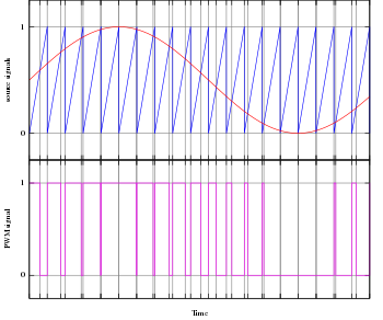 The simplest way to generate a PWM signal is the intersective method, which requires only a sawtooth or a triangle waveform (easily generated using a simple oscillator) and a comparator.
When the value of the reference signal (the red sine wave in figure 2)
is more than the modulation waveform (blue), the PWM signal (magenta) is
in the high state, otherwise it is in the low state.
The simplest way to generate a PWM signal is the intersective method, which requires only a sawtooth or a triangle waveform (easily generated using a simple oscillator) and a comparator.
When the value of the reference signal (the red sine wave in figure 2)
is more than the modulation waveform (blue), the PWM signal (magenta) is
in the high state, otherwise it is in the low state.
Applications
Servos
PWM is used to control servomechanisms; see servo control.
Pulses of various lengths (the information itself) will be sent at regular intervals (the carrier frequency of the modulation).
One method measures the output voltage. When it is lower than the desired voltage, it turns on the switch. When the output voltage is above the desired voltage, it turns off the switch.
FEEL FREE TO POST ANY DOUBTS AND COMMENT BELOW
Pulse Width Modulation, or PWM, is a technique for getting analog results with digital means. Digital control is used to create a square wave, a signal switched between on and off. This on-off pattern can simulate voltages in between full on (5 Volts) and off (0 Volts) by changing the portion of the time the signal spends on versus the time that the signal spends off. The duration of "on time" is called the pulse width. To get varying analog values, you change, or modulate, that pulse width. If you repeat this on-off pattern fast enough with an LED for example, the result is as if the signal is a steady voltage between 0 and 5v controlling the brightness of the LED.
for example :
Principle
, with period , low value , a high value and a duty cycle D (see figure 1), the average value of the waveform is given by: is a pulse wave, its value is for and for . The above expression then becomes:
 as . From this, it is obvious that the average value of the signal () is directly dependent on the duty cycle D.
A simple method to generate the PWM pulse train corresponding to
a given signal is the intersective PWM: the signal (here the red sine
wave) is compared with a sawtooth waveform (blue). When the latter is
less than the former, the PWM signal (magenta) is in high state (1).
Otherwise it is in the low state (0).
Applications
Servos
PWM is used to control servomechanisms; see servo control.
Telecommunications
In telecommunications, PWM is a form of signal modulation where the widths of the pulses correspond to specific data values encoded at one end and decoded at the other.Pulses of various lengths (the information itself) will be sent at regular intervals (the carrier frequency of the modulation).
          _      _      _      _      _      _      _      _
         | |    | |    | |    | |    | |    | |    | |    | |
Clock    | |    | |    | |    | |    | |    | |    | |    | |
       __| |____| |____| |____| |____| |____| |____| |____| |____

                 _      __     ____          ____   _
PWM signal      | |    |  |   |    |        |    | | |
                | |    |  |   |    |        |    | | |
       _________| |____|  |___|    |________|    |_| |___________

Data       0     1       2      4      0      4     1      0
The inclusion of a clock signal
is not necessary, as the leading edge of the data signal can be used as
the clock if a small offset is added to the data value in order to
avoid a data value with a zero length pulse. _ __ ___ _____ _ _____ __ _
| | | | | | | | | | | | | | | |
PWM signal | | | | | | | | | | | | | | | |
__| |____| |___| |__| |_| |____| |_| |___| |_____
Data 0 1 2 4 0 4 1 0
Power delivery
PWM can be used to control the amount of power delivered to a load without incurring the losses that would result from linear power delivery by resistive means. Drawbacks to this technique are that the power drawn by the load is not constant but rather discontinuous (see Buck converter), and energy delivered to the load is not continuous either. However, the load may be inductive, and with a sufficiently high frequency and when necessary using additional passive electronic filters, the pulse train can be smoothed and average analog waveform recovered. Power flow into the load can be continuous. Power flow from the supply is not constant and will require energy storage on the supply side in most cases. (In the case of an electrical circuit, a capacitor to absorb energy stored in (often parasitic) supply side inductance.)Voltage regulation
Main article: Switched-mode power supply
PWM is also used in efficient voltage regulators.
By switching voltage to the load with the appropriate duty cycle, the
output will approximate a voltage at the desired level. The switching
noise is usually filtered with an inductor and a capacitor.One method measures the output voltage. When it is lower than the desired voltage, it turns on the switch. When the output voltage is above the desired voltage, it turns off the switch.
Audio effects and amplification
PWM is sometimes used in sound (music) synthesis, in particular subtractive synthesis, as it gives a sound effect similar to chorus or slightly detuned oscillators played together. (In fact, PWM is equivalent to the difference of two sawtooth waves with one of them inverted.[1]) The ratio between the high and low level is typically modulated with a low frequency oscillator. In addition, varying the duty cycle of a pulse waveform in a subtractive-synthesis instrument creates useful timbral variations. Some synthesizers have a duty-cycle trimmer for their square-wave outputs, and that trimmer can be set by ear; the 50% point (true square wave) was distinctive, because even-numbered harmonics essentially disappear at 50%. Pulse waves, usually 50%, 25%, and 12.5%, make up the soundtracks of classic video games.FEEL FREE TO POST ANY DOUBTS AND COMMENT BELOW
No comments:
Post a Comment