Monday, 21 November 2016

WHAT IS A TRANSISTOR?

WHAT IS A TRANSISTOR?

A transistor is a semiconductor device used to amplify or switch electronic signals and electrical power. It is composed of semiconductor material usually with at least three terminals for connection to an external circuit. A voltage or current applied to one pair of the transistor's terminals controls the current through another pair of terminals. Because the controlled (output) power can be higher than the controlling (input) power, a transistor can amplify a signal. Today, some transistors are packaged individually, but many more are found embedded in integrated circuits.


Importance

A Darlington transistor opened up so the actual transistor chip (the small square) can be seen inside. A Darlington transistor is effectively two transistors on the same chip. One transistor is much larger than the other, but both are large in comparison to transistors in large-scale integration because this particular example is intended for power applications.
The transistor is the key active component in practically all modern electronics. Many consider it to be one of the greatest inventions of the 20th century.[29] Its importance in today's society rests on its ability to be mass-produced using a highly automated process (semiconductor device fabrication) that achieves astonishingly low per-transistor costs. The invention of the first transistor at Bell Labs was named an IEEE Milestone in 2009.
Although several companies each produce over a billion individually packaged (known as discrete) transistors every year, the vast majority of transistors are now produced in integrated circuits (often shortened to IC, microchips or simply chips), along with diodes, resistors, capacitors and other electronic components, to produce complete electronic circuits. A logic gate consists of up to about twenty transistors whereas an advanced microprocessor, as of 2009, can use as many as 3 billion transistors (MOSFETs).]
The transistor's low cost, flexibility, and reliability have made it a ubiquitous device. Transistorized mechatronic circuits have replaced electromechanical devices in controlling appliances and machinery. It is often easier and cheaper to use a standard microcontroller and write a computer program to carry out a control function than to design an equivalent mechanical control function.


Simplified operation


Transistor as a switch

BJT used as an electronic switch, in grounded-emitter configuration.
Transistors are commonly used in digital circuits as electronic switches which can be either in an "on" or "off" state, both for high-power applications such as switched-mode power supplies and for low-power applications such as logic gates. Important parameters for this application include the current switched, the voltage handled, and the switching speed, characterised by the rise and fall times.
In a grounded-emitter transistor circuit, such as the light-switch circuit shown, as the base voltage rises, the emitter and collector currents rise exponentially. The collector voltage drops because of reduced resistance from collector to emitter. If the voltage difference between the collector and emitter were zero (or near zero), the collector current would be limited only by the load resistance (light bulb) and the supply voltage. This is called saturation because current is flowing from collector to emitter freely. When saturated, the switch is said to be on.
Providing sufficient base drive current is a key problem in the use of bipolar transistors as switches. The transistor provides current gain, allowing a relatively large current in the collector to be switched by a much smaller current into the base terminal. The ratio of these currents varies depending on the type of transistor, and even for a particular type, varies depending on the collector current. In the example light-switch circuit shown, the resistor is chosen to provide enough base current to ensure the transistor will be saturated.
In a switching circuit, the idea is to simulate, as near as possible, the ideal switch having the properties of open circuit when off, short circuit when on, and an instantaneous transition between the two states. Parameters are chosen such that the "off" output is limited to leakage currents too small to affect connected circuitry; the resistance of the transistor in the "on" state is too small to affect circuitry; and the transition between the two states is fast enough not to have a detrimental effect.

Transistor as an amplifier

Amplifier circuit, common-emitter configuration with a voltage-divider bias circuit.
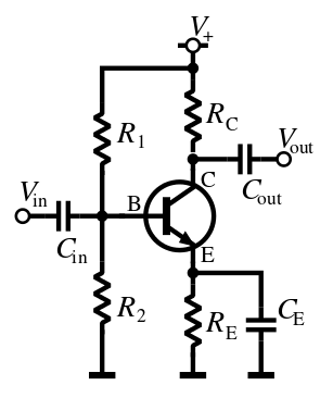
The common-emitter amplifier is designed so that a small change in voltage (Vin) changes the small current through the base of the transistor; the transistor's current amplification combined with the properties of the circuit mean that small swings in Vin produce large changes in Vout.
Various configurations of single transistor amplifier are possible, with some providing current gain, some voltage gain, and some both.
From mobile phones to televisions, vast numbers of products include amplifiers for sound reproduction, radio transmission, and signal processing. The first discrete-transistor audio amplifiers barely supplied a few hundred milliwatts, but power and audio fidelity gradually increased as better transistors became available and amplifier architecture evolved.
Modern transistor audio amplifiers of up to a few hundred watts are common and relatively inexpensive.


Advantages

The key advantages that have allowed transistors to replace vacuum tubes in most applications are
  • no cathode heater (which produces the characteristic orange glow of tubes), reducing power consumption, eliminating delay as tube heaters warm up, and immune from cathode poisoning and depletion;
  • very small size and weight, reducing equipment size;
  • large numbers of extremely small transistors can be manufactured as a single integrated circuit;
  • low operating voltages compatible with batteries of only a few cells;
  • circuits with greater energy efficiency are usually possible. For low-power applications (e.g., voltage amplification) in particular, energy consumption can be very much less than for tubes;
  • inherent reliability and very long life; tubes always degrade and fail over time. Some transistorized devices have been in service for more than 50 years[citation needed] ;

Limitations

Transistors have the following limitations:
  • silicon transistors can age and fail;[35]
  • high-power, high-frequency operation, such as that used in over-the-air television broadcasting, is better achieved in vacuum tubes due to improved electron mobility in a vacuum;
  • solid-state devices are susceptible to damage from very brief electrical and thermal events, including electrostatic discharge in handling; vacuum tubes are electrically much more rugged;
  • sensitivity to radiation and cosmic rays (special radiation-hardened chips are used for spacecraft devices);
  • vacuum tubes in audio applications create significant lower-harmonic distortion, the so-called tube sound, which some people prefer.[36]

Types

BJT PNP symbol.svg PNP JFET P-Channel Labelled.svg P-channel
BJT NPN symbol.svg NPN JFET N-Channel Labelled.svg N-channel
BJT
JFET
BJT and JFET symbols
JFET P-Channel Labelled.svg IGFET P-Ch Enh Labelled.svg IGFET P-Ch Enh Labelled simplified.svg IGFET P-Ch Dep Labelled.svg P-channel
JFET N-Channel Labelled.svg IGFET N-Ch Enh Labelled.svg IGFET N-Ch Enh Labelled simplified.svg IGFET N-Ch Dep Labelled.svg N-channel
JFET MOSFET enh MOSFET dep
JFET and MOSFET symbols
Transistors are categorized by
Hence, a particular transistor may be described as silicon, surface-mount, BJT, n–p–n, low-power, high-frequency switch.
A popular way to remember which symbol represents which type of transistor is to look at the arrow and how it is arranged. Within an NPN transistor symbol, the arrow will Not Point iN. Conversely, within the PNP symbol you see that the arrow Points iN Proudly.

Bipolar junction transistor (BJT)

Bipolar transistors are so named because they conduct by using both majority and minority carriers.

Field-effect transistor (FET)

Main articles: Field-effect transistor, MOSFET, and JFET
Operation of a FET and its Id-Vg curve. At first, when no gate voltage is applied. There is no inversion electron in the channel, the device is OFF. As gate voltage increase, inversion electron density in the channel increase, current increase, the device turns on.

Usage of bipolar and field-effect transistors

The bipolar junction transistor (BJT) was the most commonly used transistor in the 1960s and 70s. Even after MOSFETs became widely available, the BJT remained the transistor of choice for many analog circuits such as amplifiers because of their greater linearity and ease of manufacture. In integrated circuits, the desirable properties of MOSFETs allowed them to capture nearly all market share for digital circuits. Discrete MOSFETs can be applied in transistor applications, including analog circuits, voltage regulators, amplifiers, power transmitters and motor drivers.


FEEL FREE TO POST ANY COMMENTS AND ASK YOUR DOUBTS


Sunday, 13 November 2016

Ultrasonic Range detector using Arduino and the SR04 Ultrasonic sensor


Step 1: Connecting the SR04 Ultrasonic Sensor to the Arduino

Connecting the SR04  Ultrasonic Sensor to the Arduino

Step 2: Parts List

1               Arduino uno R3, or any Arduino for that matter
1               SR04 Ultrasonic Sensor
1               breadboard
4               Jumper Wires

Step 3: Connect Ultrasonic Sensor to Arduino

Connect  Ultrasonic Sensor to Arduino
You Need 4 Jumper wires to conect the SR04 Ultrasonic Sensor to the Arduino:

1  From the SR04  VCC pin to the Arduino 5v
1 From the SR04  GND pin to the Arduino GND
1 From the SR04  TRG pin to the Arduino Digital pin 12
1 From the SR04  ECHO pin to the Arduino Digital pin 11


Next Step, load the Software library and sketches.

Step 4: Step 4 Download SR04 Library and install to Arduino IDE

 DOWNLOAD HERE

Step 4 Download SR04 Library and install to Arduino IDE
 

You should now be able to see the  library and examples in  select File > Examples > NewPing > NewPingexample sketch.
load the sketch to your Arduino.

If you were successful at installing the libraries, and loading the NewPingexample sketch,  Compile the sketch  by clicking on the verify button and make sure there are no errors.

It's time to connect your Arduino to your PC using the USB cable.  Click on the upload button  to upload the sketch to the Arduino.

Once uploaded to the Arduino, open the serial monitor, and you should see the distance  data stream   coming from the sensor. 
 
 
DO SHARE AND LIKE AND COMMENT FEEL FREE TO POST DOUBTS

Saturday, 12 November 2016

HOW TO USE A LCD WITH ARDUINO


USING LCD

The LiquidCrystal library allows you to control LCD displays that are compatible with the Hitachi HD44780 driver. There are many of them out there, and you can usually tell them by the 16-pin interface.

The LCDs have a parallel interface, meaning that the microcontroller has to manipulate several interface pins at once to control the display. The interface consists of the following pins: 

A register select (RS) pin that controls where in the LCD's memory you're writing data to. You can select either the data register, which holds what goes on the screen, or an instruction register, which is where the LCD's controller looks for instructions on what to do next.
A Read/Write (R/W) pin that selects reading mode or writing mode
An Enable pin that enables writing to the registers
8 data pins (D0 -D7). The states of these pins (high or low) are the bits that you're writing to a register when you write, or the values you're reading when you read.
There's also a display constrast pin (Vo), power supply pins (+5V and Gnd) and LED Backlight (Bklt+ and BKlt-) pins that you can use to power the LCD, control the display contrast, and turn on and off the LED backlight, respectively.
The process of controlling the display involves putting the data that form the image of what you want to display into the data registers, then putting instructions in the instruction register. The LiquidCrystal Library simplifies this for you so you don't need to know the low-level instructions.
The LCDs can be controlled in two modes: 4-bit or 8-bit. The 4-bit mode requires seven I/O pins from the Arduino, while the 8-bit mode requires 11 pins. For displaying text on the screen, you can do most everything in 4-bit mode, so example shows how to control a 2x16 LCD in 4-bit mode. 

THINGS NEED IN THIS PROJECT :-

  • Arduino or Genuino Board
  • LCD Screen
  • pin headers to solder to the LCD display pins
  • 10k ohm potentiometer
  • 220 ohm resistor
  • JUMPER WIRES
  • breadboard
 CIRCUIT OR WIRING:-
  
Before wiring the LCD screen to your Arduino or Genuino board we suggest to solder a pin header strip to the 14 (or 16) pin count connector of the LCD screen, as you can see in the image above.
To wire your LCD screen to your board, connect the following pins:
  • LCD RS pin to digital pin 12
  • LCD Enable pin to digital pin 11
  • LCD D4 pin to digital pin 5
  • LCD D5 pin to digital pin 4
  • LCD D6 pin to digital pin 3
  • LCD D7 pin to digital pin 2
Additionally, wire a 10k pot to +5V and GND, with it's wiper (output) to LCD screens VO pin (pin3). A 220 ohm resistor is used to power the backlight of the display, usually on pin 15 and 16 of the LCD connector

 CIRCUIT DIAGRAM:-


 CODE :                                                                                                                           

// include the library code:
#include <LiquidCrystal.h>

// initialize the library with the numbers of the interface pins
LiquidCrystal lcd(12, 11, 5, 4, 3, 2);

void setup() {
  // set up the LCD's number of columns and rows:
  lcd.begin(16, 2);
  // Print a message to the LCD.
  lcd.print("hello, world!");
}

void loop() {
  // set the cursor to column 0, line 1
  // (note: line 1 is the second row, since counting begins with 0):
  lcd.setCursor(0, 1);
  // print the number of seconds since reset:
  lcd.print(millis() / 1000);
}

EXPLANATION                                                                         

The lcd.begin(16,2) command set up the LCD number of columns and rows. For example, if you have an LCD with 20 columns and 4 rows (20x4) you will have to change this to lcd.begin(20x4).

The lcd.print("--message--") command print a message to first column and row of lcd display. The "message" must have maximum length equal to lcd columns number. For example, for 16 columns display max length is equal with 16 and for 20 columns display max length is equal with 20.

The lcd.setCursor(0,1) command will set cursor to first column of second row. If you have an LCD 20x4 and you want to print a message to column five and third row you have to use: lcd.setCursor(4,2).


FEEL FREE TO POST ANY COMMENTS. DO LIKE SHARE AND SUBSCRIBE FOR MORE


Friday, 11 November 2016

LED AND RESISTORS : ELECTRONICS BASICS

WHAT IS LED?

A light-emitting diode (LED) is a two-lead semiconductor light source. It is a p–n junction diode, which emits light when activated.[4] When a suitable voltage is applied to the leads, electrons are able to recombine with electron holes within the device, releasing energy in the form of photons. This effect is called electroluminescence, and the color of the light (corresponding to the energy of the photon) is determined by the energy band gap of the semiconductor.

 Recent developments

Appearing as practical electronic components in 1962,[6] the earliest LEDs emitted low-intensity infrared light. Infrared LEDs are still frequently used as transmitting elements in remote-control circuits, such as those in remote controls for a wide variety of consumer electronics. The first visible-light LEDs were also of low intensity, and limited to red. Modern LEDs are available across the visible, ultraviolet, and infrared wavelengths, with very high brightness

BLOCK DIAGRAM

Working principle

The inner workings of an LED, showing circuit (top) and band diagram (bottom)
A P-N junction can convert absorbed light energy into a proportional electric current. The same process is reversed here (i.e. the P-N junction emits light when electrical energy is applied to it). This phenomenon is generally called electroluminescence, which can be defined as the emission of light from a semi-conductor under the influence of an electric field. The charge carriers recombine in a forward-biased P-N junction as the electrons cross from the N-region and recombine with the holes existing in the P-region. Free electrons are in the conduction band of energy levels, while holes are in the valence energy band. Thus the energy level of the holes will be lesser than the energy levels of the electrons. Some portion of the energy must be dissipated in order to recombine the electrons and the holes. This energy is emitted in the form of heat and light.
The electrons dissipate energy in the form of heat for silicon and germanium diodes but in gallium arsenide phosphide (GaAsP) and gallium phosphide (GaP) semiconductors, the electrons dissipate energy by emitting photons. If the semiconductor is translucent, the junction becomes the source of light as it is emitted, thus becoming a light-emitting diode, but when the junction is reverse biased no light will be produced by the LED and, on the contrary, the device may also be damaged.


    Advantages

  • Efficiency: LEDs emit more lumens per watt than incandescent light bulbs. The efficiency of LED lighting fixtures is not affected by shape and size unlike fluorescent light bulbs or tubes.
  • Color: LEDs can emit light of an intended color without using any color filters as traditional lighting methods need. This is more efficient and can lower initial costs.
  • Size: LEDs can be very small (smaller than 2 mm2) and are easily attached to printed circuit boards.
  • Warmup time: LEDs light up very quickly. A typical red indicator LED will achieve full brightness in under a microsecond.LEDs used in communications devices can have even faster response times.
  • Cycling: LEDs are ideal for uses subject to frequent on-off cycling, unlike incandescent and fluorescent lamps that fail faster when cycled often, or high-intensity discharge lamps (HID lamps) that require a long time before restarting.
  • Dimming: LEDs can very easily be dimmed either by pulse-width modulation or lowering the forward current This pulse-width modulation is why LED lights, particularly headlights on cars, when viewed on camera or by some people, appear to be flashing or flickering. This is a type of stroboscopic effect.
 

    Disadvantages

  • Initial price: LEDs are currently slightly more expensive (price per lumen) on an initial capital cost basis, than other lighting technologies. As of March 2014, at least one manufacturer claims to have reached $1 per kilolumen. The additional expense partially stems from the relatively low lumen output and the drive circuitry and power supplies needed.
  • Temperature dependence: LED performance largely depends on the ambient temperature of the operating environment – or thermal management properties. Overdriving an LED in high ambient temperatures may result in overheating the LED package, eventually leading to device failure. An adequate heat sink is needed to maintain long life. This is especially important in automotive, medical, and military uses where devices must operate over a wide range of temperatures, which require low failure rates. Toshiba has produced LEDs with an operating temperature range of −40 to 100 °C, which suits the LEDs for both indoor and outdoor use in applications such as lamps, ceiling lighting, street lights, and floodlights
  • Voltage sensitivity: LEDs must be supplied with a voltage above their threshold voltage and a current below their rating. Current and lifetime change greatly with a small change in applied voltage. They thus require a current-regulated supply (usually just a series resistor for indicator LEDs).
  • Color rendition: Most cool-white LEDs have spectra that differ significantly from a black body radiator like the sun or an incandescent light. The spike at 460 nm and dip at 500 nm can cause the color of objects to be perceived differently under cool-white LED illumination than sunlight or incandescent sources, due to metamerismred surfaces being rendered particularly poorly by typical phosphor-based cool-white LEDs.
  • Area light source: Single LEDs do not approximate a point source of light giving a spherical light distribution, but rather a lambertian distribution. So LEDs are difficult to apply to uses needing a spherical light field; however, different fields of light can be manipulated by the application of different optics or "lenses". LEDs cannot provide divergence below a few degrees. In contrast, lasers can emit beams with divergences of 0.2 degrees or less
  • Electrical polarity: Unlike incandescent light bulbs, which illuminate regardless of the electrical polarity, LEDs will only light with correct electrical polarity. To automatically match source polarity to LED devices, rectifiers can be used.

RESISTANCE 

WHAT IS A RESISTOR? 

A resistor is a passive two-terminal electrical component that implements electrical resistance as a circuit element. In electronic circuits, resistors are used to reduce current flow, adjust signal levels, to divide voltages, bias active elements, and terminate transmission lines, among other uses. High-power resistors that can dissipate many watts of electrical power as heat may be used as part of motor controls, in power distribution systems, or as test loads for generators. Fixed resistors have resistances that only change slightly with temperature, time or operating voltage. Variable resistors can be used to adjust circuit elements (such as a volume control or a lamp dimmer), or as sensing devices for heat, light, humidity, force, or chemical activity.

Electronic symbols and notation

Two typical schematic diagram symbols are as follows:

Theory of operation

The hydraulic analogy compares electric current flowing through circuits to water flowing through pipes. When a pipe (left) is clogged with hair (right), it takes a larger pressure to achieve the same flow of water. Pushing electric current through a large resistance is like pushing water through a pipe clogged with hair: It requires a larger push (voltage) to drive the same flow (electric current).

Ohm's law

Main article: Ohm's law
The behavior of an ideal resistor is dictated by the relationship specified by Ohm's law:
V=I*R
Ohm's law states that the voltage (V) across a resistor is proportional to the current (I), where the constant of proportionality is the resistance (R). For example, if a 300 ohm resistor is attached across the terminals of a 12 volt battery, then a current of 12 / 300 = 0.04 amperes flows through that resistor.
Practical resistors also have some inductance and capacitance which affect the relation between voltage and current in alternating current circuits.
The ohm (symbol: Ω) is the SI unit of electrical resistance, named after Georg Simon Ohm. An ohm is equivalent to a volt per ampere. Since resistors are specified and manufactured over a very large range of values, the derived units of milliohm (1 mΩ = 10−3 Ω), kilohm (1 kΩ = 103 Ω), and megohm (1 MΩ = 106 Ω) are also in common usage.

Series and parallel resistors


The total resistance of resistors connected in series is the sum of their individual resistance values.
A diagram of several resistors, connected end to end, with the same amount of current going through each
                        R=R1+R2+.......RN
  
The total resistance of resistors connected in parallel is the reciprocal of the sum of the reciprocals of the individual resistors.
A diagram of several resistors, side by side, both leads of each connected to the same wires

\frac{1}{R_\mathrm{eq}} = \frac{1}{R_1} + \frac{1}{R_2} + \cdots +  \frac{1}{R_n}.
For example, a 10 ohm resistor connected in parallel with a 5 ohm resistor and a 15 ohm resistor produces 1/1/10 + 1/5 + 1/15 ohms of resistance, or 30/11 = 2.727 ohms.
A resistor network that is a combination of parallel and series connections can be broken up into smaller parts that are either one or the other. Some complex networks of resistors cannot be resolved in this manner, requiring more sophisticated circuit analysis. Generally, the Y-Δ transform, or matrix methods can be used to solve such problems

Power dissipation

At any instant, the power P (watts) consumed by a resistor of resistance R (ohms) is calculated as: 
P =I^2 R = I V =  \frac{V^2}{R}
where V (volts) is the voltage across the resistor and I (amps) is the current flowing through it. Using Ohm's law, the two other forms can be derived. This power is converted into heat which must be dissipated by the resistor's package before its temperature rises excessively.
Resistors are rated according to their maximum power dissipation. Discrete resistors in solid-state electronic systems are typically rated as 1/10, 1/8, or 1/4 watt. They usually absorb much less than a watt of electrical power and require little attention to their power rating.


Resistors required to dissipate substantial amounts of power, particularly used in power supplies, power conversion circuits, and power amplifiers, are generally referred to as power resistors; this designation is loosely applied to resistors with power ratings of 1 watt or greater. Power resistors are physically larger and may not use the preferred values, color codes, and external packages described below.
If the average power dissipated by a resistor is more than its power rating, damage to the resistor may occur, permanently altering its resistance.


FEEL FREE TO POST ANY COMMENTS. LIKE SHARE SUBSCRIBE FOR FUTURE POSTS


FADING LED USING PWM:PULSE WITH MODULATION


Fade an LED with Pulse Width Modulation using analogWrite()

IN THIS PROJECT U WILL NEED :- 

1.ARDUINO

2.LED

3.220 OHM RESISTOR

4.JUMPER WIRES

CIRCUIT PICTURE :-  


Step-by-Step Instructions

  1. Take the short leg of the LED and insert it in the GND pin.
  2. Take either leg of the resistor and place it in pin 9.
  3. Connect the long leg of the LED with the other leg of the resistor using an alligator clip
  4. Plug the Arduino into your computer with the USB cable
  5. Open up the Arduino IDE

CODE :-
  
  This example shows how to fade an LED on pin 9
using the analogWrite() function.
 
This example code is in the public domain.
*/
 
int led = 9;           // the pin that the LED is attached to
int brightness = 0;    // how bright the LED is
int fadeAmount = 5;    // how many points to fade the LED by
 
// the setup routine runs once when you press reset:
void setup() {
  // declare pin 9 to be an output:
  pinMode(led, OUTPUT);
}
 
// the loop routine runs over and over again forever:
void loop() {
  // set the brightness of pin 9:
  analogWrite(led, brightness);
 
  // change the brightness for next time through the loop:
  brightness = brightness + fadeAmount;
 
  // reverse the direction of the fading at the ends of the fade:
  if (brightness == 0 || brightness == 255) {
    fadeAmount = -fadeAmount ;
  }
  // wait for 30 milliseconds to see the dimming effect
  delay(30);
}
 
 6.Click the Verify button (top left). The button will turn orange and then blue once finished.
 7.Click the Upload button. The button will turn orange and then blue when finished.
 
 
EXPLANATION : 
 
Where the real action happens is in loop().
The first function we encounter in the loop() is analogWrite(). This function invokes the Pulse Width Modulation capabilities of the Arduino board. Pulse Width Modulation basically adjusts the power output at the pin. So you can have a lot of power or a little power applied at the pin, it’s your call, just tell the analogWrite() function which pin to modulate and how much power you want to be applied. The scale is from 0 to 255 with zero being the lowest power setting and 255 being the highest.  


                analogWrite(pin, value);
You can utilize analogWrite() with pins 3, 5, 6, 9, 10 and 11 – recall there is a “PWM” or “~” next to the pin number on the board.
In this sketch we use the arguments:
The first thing we do in the loop is write a value to pin 9 (recall that led holds the number 9) where we have our LED attached (through a resistor) – and we set the value to 0 (zero is what our brightness variable initially holds). This will keep our LED dark to start with.
Key Points about the analogWrite function
 
FEEL FREE TO POST ANY DOUBTS AND COMMENT BELOW FOR SUGGESTION .
DO CHECK OUT MY OTHER TUTORIALS AND SUBSCRIBE FOR MORE


Thursday, 10 November 2016

How to use Humidity and Temperature (DHT11) Sensor to Arduino and including DHT11 Library.

WHAT IS DHT11 SENSOR?

The DHT11 is a basic, ultra low-cost digital temperature and humidity sensor. It uses a capacitive humidity sensor and a thermistor to measure the surrounding air, and spits out a digital signal on the data pin (no analog input pins needed). Its fairly simple to use, but requires careful timing to grab data.

THIS PROJECT FOLLOWING HARDWARE COMPONENTS:-

1)  DTH11 Humidity and Temperature Sensor
2)  Arduino UNO
3) JUMPER Wires

NOTE : YOU WILL ALSO NEET TO DOWNLOAD DHT LIBRARY AND IMPORT IN YOUR PROGRAM.

DOWNLOAD FROM   HERE


Go to Sketch--> Include Library --> Add Zip File
As shown in the above screen shot please browse the ZIP file and include the library after including the library.
Close the Arduino IDE and open it again then you will find the library included.

CODE :

 
#include<dht.h>
dht DHT;

// if you require to change the pin number, Edit the pin with your arduino pin.
#define DHT11_PIN 3
void setup() {
Serial.begin(9600);
Serial.println("welcome to TechPonder Humidity and temperature Detector"); }
void loop() { // READ DATA
int chk = DHT.read11(DHT11_PIN);
Serial.println(" Humidity " );
Serial.println(DHT.humidity, 1);
Serial.println(" Temparature ");
Serial.println(DHT.temperature, 1);
delay(2000);
}


 Program and Results

Picture of Program and Results
humidity and temparature values.jpg
 
FEEL FREE TO POST ANY COMMENTS OR DOUBTS BELOW AND SUBSCRIBE FOR MORE TUTORIALS